deutsche Version
at moment not available
HF-Measurements
Time measurement system DerbyControl
LED-displays
traffic light system
Antenna systems
Antenna installing Services
Dummyload_Systems
Amateur radio filter systems
Referenzen
Download
Archiv
Contakt
Impressum
Contakt
Impressum
Home
9-Kanal
Preselektor,
Bandpass-Filter
Bandpass-Filter
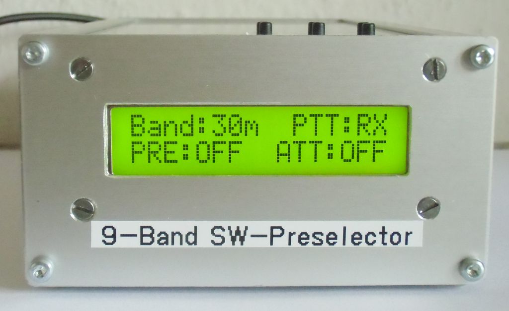
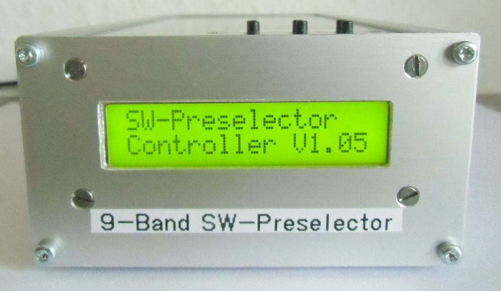
front view SW-preselector in case

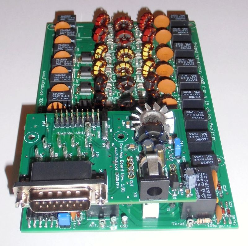
backside SW-preselector in EUROMASS II case
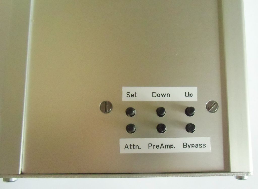
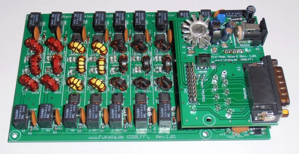
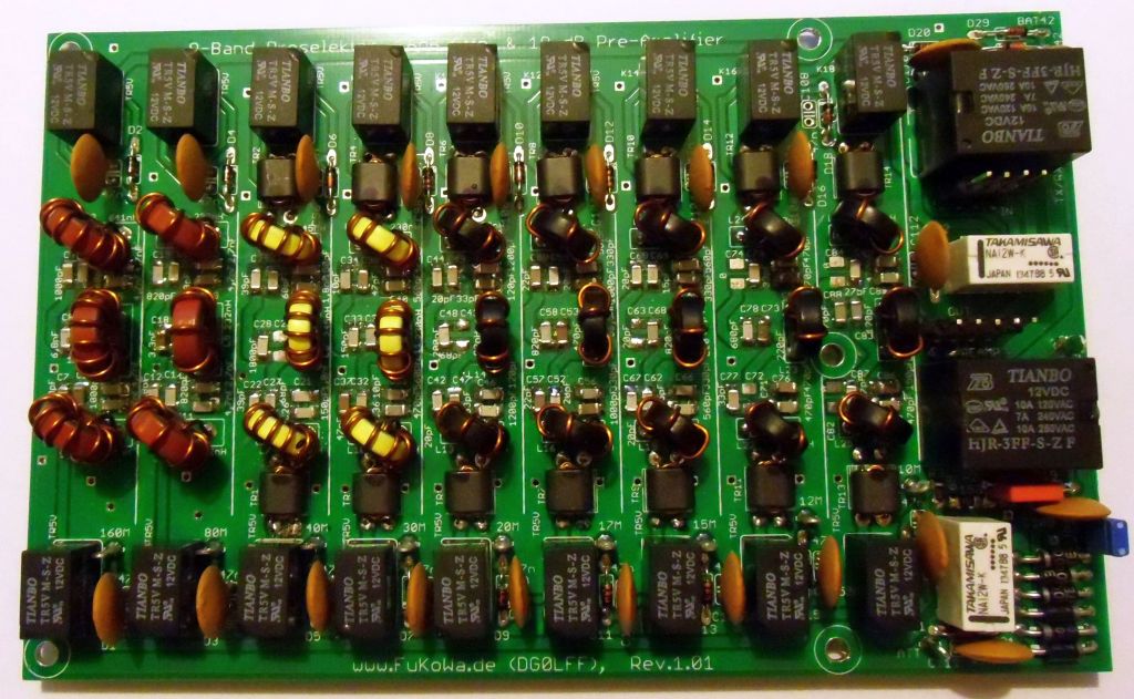
Topview SW-preselector
WARC bands include ......
160, 80, 40, 30, 20, 17, 15, 12, 10m
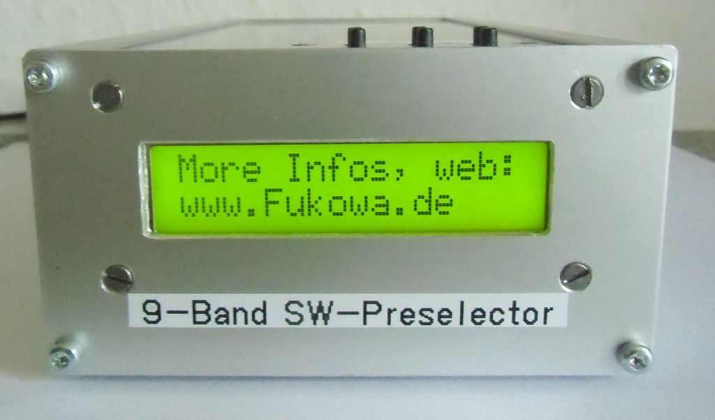
more infos here im web.....
developed for multi band or more-operator-use at your place
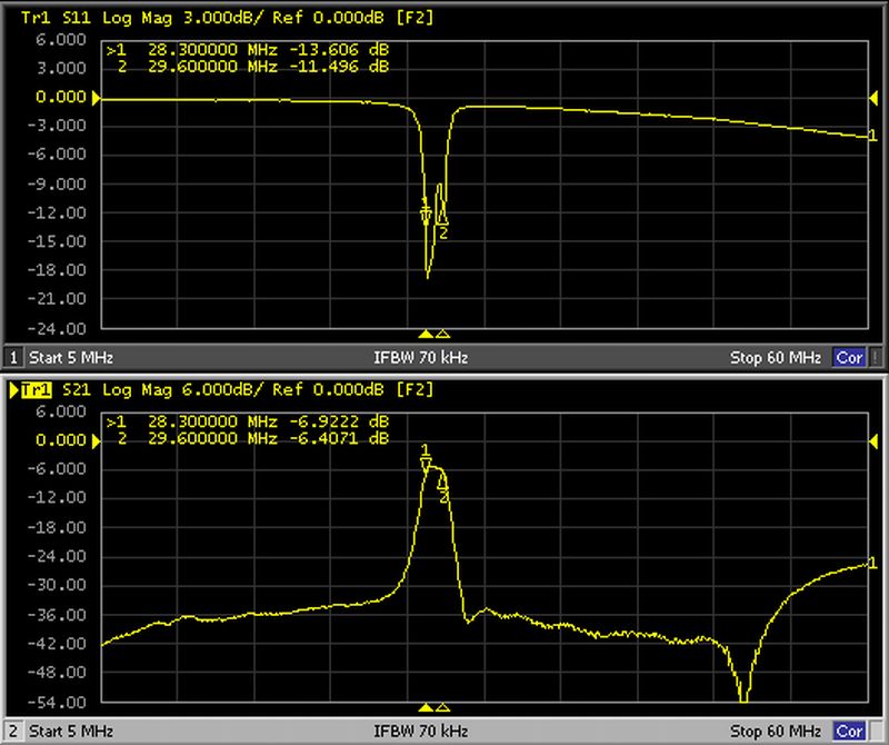
> 30dB.
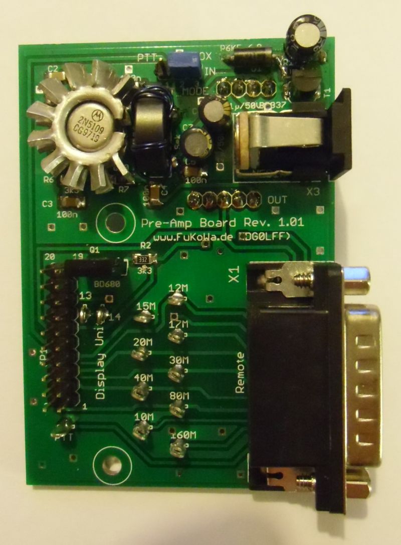
This filter have a TX / RX switching unit with up to 300 watts load, have a switchable 16dB attenuator, and 18dB pre-amplifier with OIP3 ca. 34dBm @ 22dBm, 1dB compression (W7IUV concept with a 2N5109) for strong signals
This filter is built with COG/NPO smd capacitors in size 1206 and with Amidon iron powder cores in size T44/T37.
The filter is designed for strong signals and suppress strong outband signals from other radio stations or broadcasting services.
All filters are switched with high quality signal relays and placed between two common lines for antenna input and transceiver output.
All filters ways without activation are switch off from common lines and grounded at input and output with relays.
The TX/RX switch works with the same 10A relays as we use in our low-pass filters. This system part can controlled with PTT line or integrated VOX function. The VOX circuit accept low power levels with ca. 5watts and switch to TX mode (bypass preselector) and with hold-on delay back to RX.
All control lines work in low active logic and also at remote interface available (sub-d 15 pin). If you switch a control line to ground level, the fuction is active, a open line is inactive.
OIP3= 34dBm is very good for this circuit and a lot of OM's love this concept. This circuit works with very strong signals and will not provide intermodulations when a station close to you go to TX.
Tests show us, new concepts with units from Mini Circuits or Analog Devices are not really better. The linearity and strong signal protection works only with high currents and a very linear gain curve.
The pre-amp pcb provide the remote interface (sub-d) for control and the interface for the controller / display unit and a second power supply socket.
The controller unit provide also a serial CAT interface for remote control with a PC system.
If pre-amp or attenuator not used, relay contacs shorted these circuits. When the preamp is not used, the power supply for this circuit is switch off.
All circuits have a own control input and switched over relays.
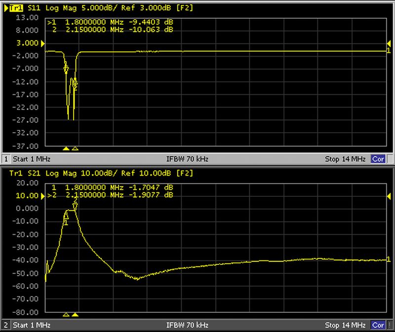
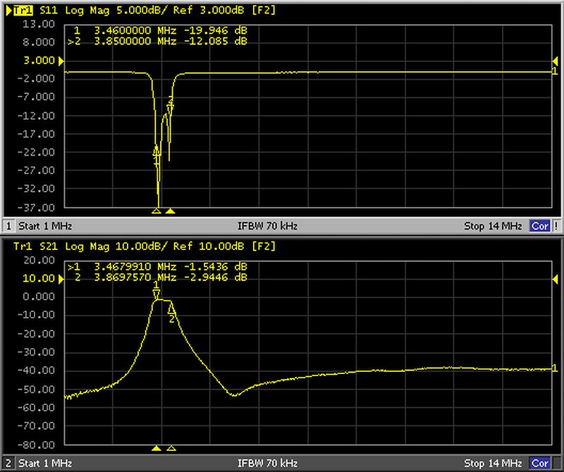
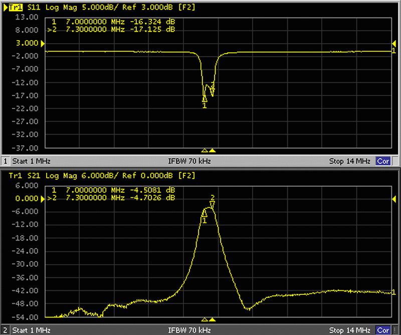
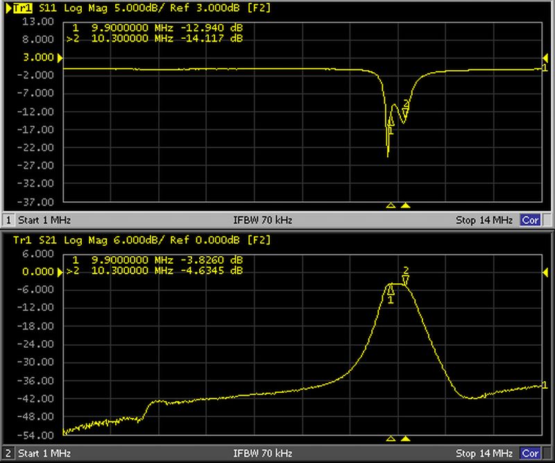
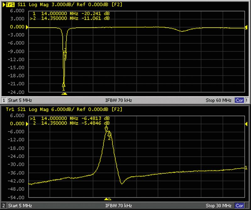
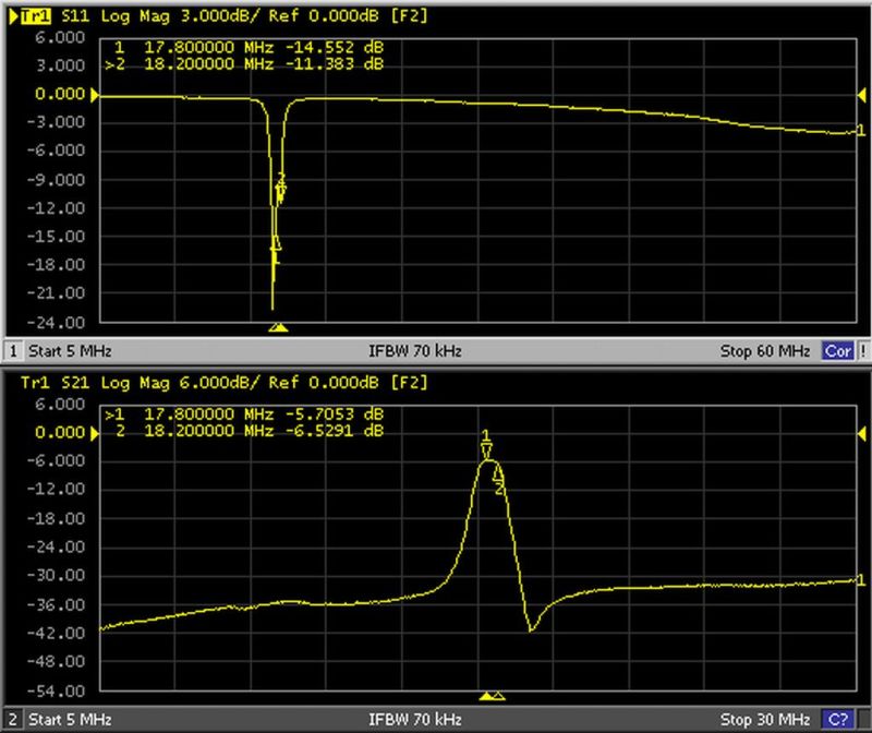
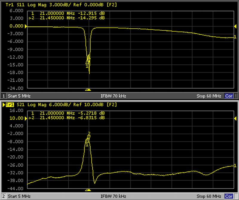
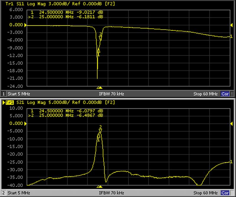
All filter curves show a pass band tuning and strong filter curves at the band ends. For the most neighbour band are the suppression close to 30dB, wide band and sub harmonic suppression are better as 30dB.